Filling the pressure: Sizing an expansion tank correctly

Filling the pressure: Sizing an expansion tank correctly

Before you get to the exciting part, you’ll need a few basic details about your system.

Here are some good questions about the correct sizing for an expansion tank from a for the conscientious installer — which I know includes all of us.

Question 1: Fill pressure vs. expansion tank size? (Or in other words, what should the loop pressure be and how much pressure should be in the expansion tank?)
Question 2: Expansion tank size vs. system fluid volume/ number of collectors? (Or, how to size the expansion tank to your solar system, including collectors, length of pipe, etc.)
Question 3: Fill pressure vs. PRVs? (How to size the pressure relief valve.)
Question 4: Fill pressure vs. head? (Does head or distance to the panel affect fill pressure?)

If you can visualize the concept of a correctly installed pressure glycol system, the answers will become more evident.

The goal is to keep the expansion tank from blowing off when the power fails on a super-hot day. To do this, the system needs to be designed along the lines of a drain-back system. (Sometimes it’s called a steam-back system.) This is the only sure way to design this to make it work correctly.

Let me explain, and your other questions will start to become clear once you understand how it works.

All plumbing coming out of the collector array MUST drop down several feet to form a thermal lock or trap for the steam in the collectors. The liquid/steam must not migrate at all. Water expands 1,130 times when it flashes. If in any way it can migrate and flow out of the collectors, it’s not possible to have a large enough expansion tank.

With this understanding, you can now start making the calculations you need. For example, a single 4’x10’ collector holds 1.3 gallons of water. So, if you have a string of eight 4’x10’ collectors, the water total is 10.4 gallons. This should have 1″ pipe (copper handbook). Never oversize the plumbing or you’ll lose control.

As the array heats and starts to flash, it will start to push the fluid back and DOWN the plumbing. Once it settles, the collectors now contain 10.4 gallons of steam volume, and about 10.4 gallons have been pushed down the plumbing into the expansion tank. Calculate expansion for the liquid in the plumbing (maybe 0 to 200°), and you now know what size the expansion tank needs to be. Or, I have an Excel spreadsheet I created years ago that will help you with the calculations. (Go to the “Sizing Tanks, Panels and WH” tab.)

Most systems have between 20 to 40 psi. Remember, every 100 feet of water has 44.4 psi. Add this to whatever you start with. Oh, and make sure you size the PRV with a good margin above set pressure.

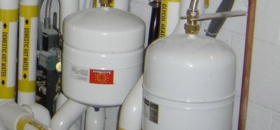
The expansion tank should have a cold unloaded pressure set before you start to fill that is close to the psi your system will be set at. You cannot change or check the pressure on an expansion tank after it has been loaded because the reading won’t be accurate.

You might get some other suggestions for setting the pressure. I know Velux and Heliodyne have some interesting guidelines. Then too, I’m not a pro on pressure glycol systems. We do drain-back every chance we can. But, European collectors generally can’t do drain-back when they have a serpentine riser inside.

Good luck — or, do it correctly and you won’t need any luck!

Row of hot water panels on a roof.

Incoming water temp can determine size of collectors, storage

As you get ready to design a solar thermal system for your home, there’s one factor you may not be considering that could make a bucket load of difference: What’s the beginning temperature of the water you’ll be heating?
In the United States’ northern climes, it’s likely 50°. In warmer, more southern climates, you’re likely beginning with 70° water.
And common sense tells us, the colder the water you start with, the more solar uumph you’ll need.
I’m asked all the time how to design a residential system. And, as I worked on the attached chart, I realized it pretty much tells you the basics of what you need to know – the size of the storage tank and the number of collectors.
This attached chart will give you an idea of what to expect. The chart allows you to determine if, for instance, you’ll be heating an 80-gallon tank in a system sized for up to three people, or a 119-gallon tank sized to serve three to five people. I chose these sizes because they are averages for family-sized systems. These numbers can be easily customized.
So, to read the chart: Say you’ve decided on an 80-gallon tank and you live in a colder area, then you’d chose line 1. And, reading across, it will tell you the number of solar collectors you’d need based on the sizes of the collectors you’d like.
Continuing this example, you decide that your home in Michigan has a large roof area and you’d like the largest collector — the 4’x10’ collector. Based on this chart you’d need two of those large collectors — or 80 square feet of collector real estate — to heat that 80-gallon storage tank.
As someone who lives in a northern climate, I shake my head sometimes knowing that we colder people all need a little extra uumph. But I know that we snow people – I live in northern Utah — will enjoy our hot water all the more.
Just as a side note, the input water temperature also has a bearing on how steep should you tip your collectors, believe it or not. If you live in 70 degree, you’ll living in a 30 to 40° latitude, so you’d use a tilt or angle of 30 to 40° for optimal performance. Likewise, those in the colder climes with colder water probably live in a 40 to50° latitude, therefore using a 40 to 50° tilt or angle.
To download an Excel file of the chart, click here.

Designing a medium-sized commercial solar thermal system for apartment complex

Other posts have discussed light commercial systems for restaurants and other similar businesses. But what if you need a solar thermal system with a bit more uumph? Here’s the recipe for a solar hot water system that would be perfect for, say, apartment buildings or hotels. It provides 330 gallons of hot water per hour, with significant backup strength.

The example I’ll discuss below is for a two-building apartment complex in Los Angeles, in which the solar thermal is targeted to provide 50 percent of hot water demand.

This size of solar thermal system — six solar collectors backed up by a Solar Phoenix modulating water heater — also works great for large restaurants or smaller hotels. To illustrate this, take a look at this case study of a solar thermal system on Catawba College in Salisbury, NC. Cost analysis indicates that energy costs at the school were cut by 58 percent. Now that’s a success story.

Here are the details on the new, low-income housing project in LA that needs a cost-effective solar thermal system:

  • Building A has a hot water demand of about 500 gpd. It’s made up of 16 two- and three-bedroom units; a laundry room with four washers; a community kitchen; and a staff restroom.
  • Building B has a hot water demand of 800 gpd. It includes 25 one-bedroom units; three washing machines; and one mop sink.

The solar thermal system I designed for this apartment complex features a 199-BTU Solar Phoenix, a highly efficient water heater that stores nearly 120 gallons of solar-heated water and kicks in as backup with more water in needed than can be heated by the sun. It’s a drainback system to guard against overheating. Also, I’ve upped the solar water storage with the addition of a second 119-gallon tank. While a light commercial system may require three to four solar collectors, for this application, I’ve recommended six 4’x’8’ collectors.

Here’s the parts list:

  • 1 ea.  Solar Phoenix, PH199-119SNHX, stainless-steel, modulating, condensing water heater with solar input
  • 1 ea. SSU-119 stainless-steel 119-gallon indirect tank
  • 1 ea. SSU-20DB stainless-steel drainback tank for overheat protection
  • 1 ea. Variable speed solar pump control with 4 sensors (8600-047)
  • 1 ea. Solar-rated anti-scalding valve (8600-068)
  • 6 ea. 4’x8’ flat plate solar collectors (FP-32SC)
  • 6 ea. FP-RM mounts (or select mounts for roof application)
  • 1 ea. Field-supplied pump that will supply 7 GPM and the lift from the drainback tank to the collectors
  • 1 ea. Field-supplied tank-to-tank transfer pump 1/2″ (I recommend a Taco 006B)
  • 1″ copper and insulation to the collectors

The control strategy uses a tank-to-tank transfer pump that will transfer the solar heat to the water heater, but will not allow the water heater to heat the storage tank. This is not a solar tank preheating a water heater; rather this is solar heating 240 gallons of storage and the water heater only firing to make up what the solar will not produce.

Data logging that allows solar production to be posted on the internet is available if the apartment building supervisors have an interest in seeing how well the solar system is performing.

In colder climates, I would recommend increasing the number of collectors to eight collectors or upgrading the size of the collectors to 4’x10’ panels.

This design for a light commercial thermal system is effective, simplified

I’m asked, more and more, to provide a solar hot water system design for light commercial systems. There is, indeed, an effective and simple design template for smaller commercial systems that need to heat up to 330 gallons of water per hour or less. The actual system this template is based on is for a fire station; the solar is designed to cover 80% to 100% of the load in a southern climate.

However, this category of light commercial could also include restaurants and cafes, hair salons and spas, grocery stores, laundromats and car washes. Some of these businesses may require even larger systems, which we’ll discuss in an upcoming blog post.

Why am I recommending this template? Because it’s the most efficient in its design, and it offers greatest simplicity in installation. It has freeze and overheat protection. Also, it requires little or no maintenance.

The virtue of this system is that solar directly heats the water to be used. Too often I’m sent designs that preheat water for some conventional water heater that can’t be heated with the solar directly.

This template includes three 4’x8′ flat-plate solar collectors. The number of panels may be adjusted according to the climate of the location. On that fire station I mentioned, because it’s in Texas, a hotter climate, fewer panels are required. If I were to spec out a similar system for a northern location, I’d possibly use one more panel or use larger panels.

This system also allows data logging with web monitoring so that its performance can be checked at any time online.

Following is the components list for this system:

  • 1 ea. Solar Phoenix, 199,000 Btu and 119 gallons (PH199-119S) stainless-steel modulating condensing water heater with solar input. Will produce continuously 335 GPH at 100° rise. If this is more than needed, use the PH130-119S
  • 1 ea. SSU-10DB stainless steel drainback tank for overheat protection (10 gallons)
  • 1 ea. Variable speed solar pump control with 4 sensors (8600-047)
  • 1 ea. Solar rated anti-scalding valve (8600-068)
  • 3 ea. 4’x8′ flat plate collectors (FP-32SC)
  • 3 ea. FP-RM mounts (or select mounts for roof application)
  • 1 ea. Field-supplied pump that will supply 4 GPM and the lift from the DB tank to the panels
  • 1″ copper and insulation to the panels

The photos below show a system using this design at Corry Station Bldg 3782 (a GSB support building) at Florida’s Eglin Air Base. The contractor is McDonald Construction of Fort Walton Beach, Fla., and they really know what they are doing (850-862-2151). The engineer was Jimmie Johnson of Johnson-Peaden Engineers, also in Fort Walton Beach. Manufacturers’ rep is Coleman-Russell.

Above shows the system at Eglin Air Base, which uses a Solar Phoenix in a simple elegant design. It includes four 4’x8′ collectors.

Template below for a drainback solar hot water system for light commercial, with three flat-plate collectors and a Solar Phoenix

Drainback system with Solar Phoenix

Drainback vs. pressure: A question for the ages

Pressure or drainback?

That’s probably the question I get asked more than any other: Should I choose the more popular pressure-glycol system, or go with a drainback system?

Here’s the answer: It depends.

Don’t you hate that kind of answer? Well, here’s a more specific answer: If the slope of the collectors and plumbing is such that all the fluid will drain out, then go with the easier and less expensive drainback design.

That doesn’t mean I favor one over the other; it really does depend on the building’s design.

Let’s backtrack for a moment. Here are definitions of each type of system.

  • Solar pressure system: Closed loop arrangement that generally has 20 psi or more at the panels. Besides the panels and the tank, basic components include check valves, expansion tank, air purge and air traps, a pressure relief valve, pump, solar control with sensors and nontoxic antifreeze.

Drainback system: Closed loop arrangement that generally has 10 psi. Besides the panels and the tank, basic components include drainback tank, a pressure relief valve, pump and a solar control with sensors. May or may not contain antifreeze.

The virtues of each system type:

  • Solar pressure system: Pressure systems generally contain glycol to provide freeze protection.
  • Drainback system: A properly designed closed-loop drainback system provides freeze protection without glycol as well as overheat protection due to the absence of fluid in the panels when either condition exists.

Let’s start with the more popular pressure glycol-filled system:

Pressure systems take time and patience to fill, charge and purge all the air out. If some air remains, controlling the flash point may be impossible.

A pressure system must be in perfect balance to handle the expansion of fluid when the pump isn’t pumping — such as a power failure or when the tank is satisfied. You must have a properly sized expansion tank that is kept at a consistent parallel pressure with the glycol loop pressure. Will this pressure stay exactly the same forever? Nope, every year you need to check and recharge the system.

And what happens if the closed-loop system pressure drops a few pounds below where you set the expansion tank pressure? The system will eventually blow antifreeze all over — via the pressure relief valve. The reason is that water-to-steam expansion is immense — 1,172% to be exact. When the pump shuts off during, say, a hot summer day, the fluid in the panels will go to boiling point and flash to steam if it is not in perfect balance.

Let’s say that we have a collector that holds one gallon of water. If the system pressure to expansion tank is maintained in concert and the pump shuts off under full sun, the panels will build heat slowly and the fluid will start to phase-change. That one gallon of water will start to phase-change and expand; it will push fluid out of the collector and down the pipes where it will stay condensed (as fluid). Eventually, you will have one gallon volume of steam in the collector and the gallon of water you pushed out will be in the expansion tank. If there is air in the system or the system pressure is not in harmony with the expansion tank, violent boiling will transfer down the plumbing, expanding several gallons of water by the aforementioned 1172%, out of control.

When the system is in balance, only a small amount of fluid will expand that immense amount, likely filling the collector’s one-gallon capacity.

Because of this, larger systems should use a constant pressure auto-fill device.

The closed-loop drainback system:

A drainback system is a fluid-filled closed loop with an air bubble and a small tank to isolate and capture the air when the pump comes on. When the pump is switched off, the heavier water drops from the panels and pushes the air bubble back up into the panels and exterior plumbing.  If the tank is satisfied or the power fails, the pump will be off, and no water will be in the panels to flash to steam. No fluid to expand, no need for expansion tank. It’s the same for freezing — when the temperature at the panels drop below freezing, there is no water in them to freeze. Fewer safety measures need to be considered.

However, a pressure glycol system will need to be considered if the slope for panels and plumbing cannot be achieved to drain all the panels’ fluid into the drainback tank.

Advantages of using some pressure

I would recommend you add a small amount of pressure in a closed loop drainback system, for two reasons. First, it will confirm you have integrity in your closed loop. If you have a completely sealed system, the air will go inert and turn mostly to harmless nitrogen.

Second, if you fill and close up the system when it’s warm, then at night when the panels get cold, the closed loop will go into negative pressure and start boiling the stored fluid in the drainback tank when it is at room temperature.

Pump and pump sizing rules change considerably with a drainback system. Pump size will be determined by the lift required to deliver from the drainback tank to the top of the panels. After the pump has overcome the lift to the panels, it’s important to have the variable solar pump speed control slow the pump down.

A variable-speed pump control should be used on both pressure and drainback systems to keep solar heat transfer to a maximum based on Delta T. Over-pumping a solar loop may void the panels’ warranty. Consider raising the drainback tank as high as possible in the building (within conditioned space) to allow a smaller pump. The pump should be sized to deliver the GPM needed for the solar and the lift from the drainback tank to the panels.

Commercial solar: With tankless water heater, you don’t pay to heat it ’til you need it

Commercial solar: With tankless water heater, you don’t pay to heat it ’til you need it

Here’s a new concept for commercial solar: a 250,000-Btu tankless water heater. It comes down to this simple philosophy: Don’t pay to heat ’til you need it. As you study this concept illustration, you’ll realize how simple this is. And, when you compare this setup to a conventional design, the cost will be half. back-up.

The Hydra Smart water allows for a gas or electric backup. In locations that have 300+ days of sunshine (all the southern U.S., for instance), I’d recommend this tankless with an electric backup. You can actually get real close to having 100% of the domestic water heating covered all by solar.

With the addition of the new Cocoon Tanks — large, super-insulated and designed to fit through any door — you can store several days of hot water. The simple drainback design lends perfect protection from freezing and overheating. Most importantly, the backup heater will rarely get used.

If you’re looking for a small domestic hot water system for your home or a client’s commercial job (laundromat, car wash or restaurant, for example) these new products and designs will dramatically cut the cost in half and make solar the big hit it should be.


Drainback with tankless is less costly, more efficient

Drainback with tankless is less costly, more efficient

Today, as part of our ongoing series of basic solar designs, we look at a drainback system using an efficient solar storage tank and a tankless water heater as backup.

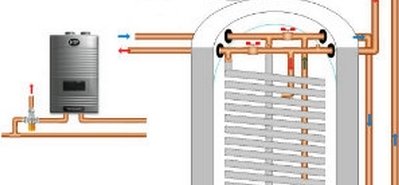
This design is fairly uncomplicated and is, perhaps, the least costly system for residential applications. For all its simplicity, it delivers freeze and overheat protection with water. It also features low heat loss.

The tank is the solar storage and the drainback tank combined. The hot water storage tank I’m using in the drawing is made of expanded polystyrene (EPS), which has an insulation factor of about R5 per inch. Dimensions of the tank are 60 inches in height and 30 inches outside diameter, with 4-inch walls. Usable Btu storage is 81 gallons,  which when filled with solar energy up to 160 degrees equals about 67,000 Btus of energy.

The system has very few components — basically the storage tank, pump, controller and collectors. The tank contains a 50-foot 1″ HX coil. Potable water is drawn through the coil, picking up heat from the contents of the tank. The backup water heating is located after the coil exits the  tank. A tankless gas or electric water heater works well as a backup, or this could be connected to any existing water heater and used as a preheat design.

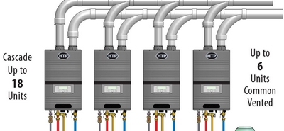
This system is an excellent choice for the HTP Hydra Smart tankless water heater. That is the tankless water heater I’ve used in the design drawing. For more information on this advanced, modulating tankless, click here.

Like other drainback designs, all plumbing must be sloped from the panels for complete drainage.

Here’s more general information on how tankless water heaters work.


Drainback solar system at airport gains every drop of energy from sun

Drainback solar system at airport gains every drop of energy from sun

Out with the old (over complicated, expensive solar). In with the new (better and more efficient solar at lower cost).

Case in point: the Minneapolis- St. Paul international Airport’s cutting-edge solar thermal system with a new innovative design approach.

Two decades ago, conventional solar called for installing a water heater or, for larger systems, a boiler that heated a tank. Later, solar morphed into separate, individual components that drew heated water into the water heater storage only if someone washed their hands. This design suffers from too much heat loss, and the solar can’t heat the water heaters to prevent them from firing. Preheating is now an outdated and inefficient design.

The new design we’re sharing today integrates the drainback tank and storage tank, reducing costs and components. At the Minneapolis-St.Paul airport, the engineering firm of Michaud, Cooley & Erickson did this with great finesse and accuracy. All 152 collectors charge the storage tank. Because the storage tank is a huge drainback tank, no energy is left to waste in a separate individual drainback vessel. That cost is eliminated too.

Conventional designs use a heat exchanger to transfer the solar BTUs into the storage devise. Any time you launder BTUs through a heat exchanger, you’ll pay an efficiency penalty. Store the pure energy until it is needed, and then use a heat exchanger to deliver it to the needed source.

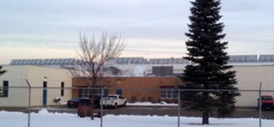
Minneapolis St. Paul International Airport drainback system